Hybrid Stepper Manufacturer


Introduction

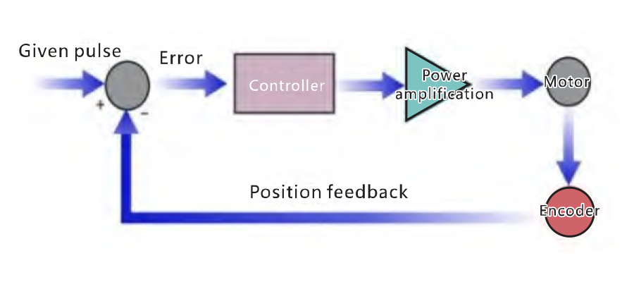
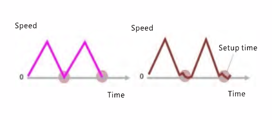
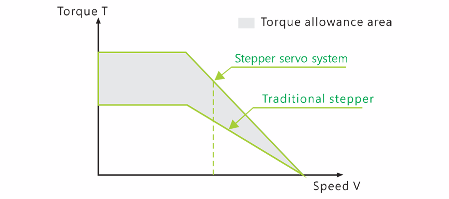
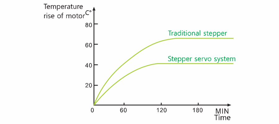
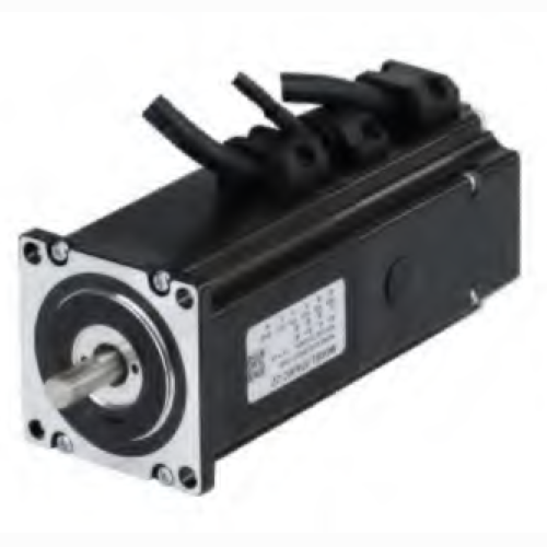
The Hybrid stepper is a control motor system that combines a common open loop stepper motor with position feedback and a servo algorithm to produce high speed, high torque, high precision, low vibration, low heating, and no step loss.

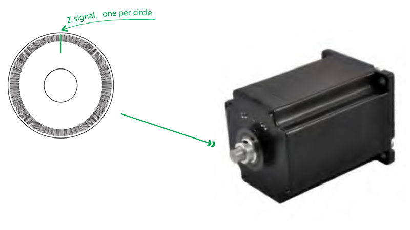
To create position feedback, a Hybrid Stepper is equipped with an optical encoder on the rear shaft of the open-loop motor.

The encoder position feedback is processed by the Hybrid stepper to achieve more precise current and position control.

Rtelligent’s Hybrid stepper systems represent a technological evolution in motion control.

They blend the cost-efficiency of traditional stepper motors with the precision of servo motors. Unlike conventional steppers, hybrid steppers incorporate a closed-loop feedback system, typically an encoder, which ensures greater accuracy and eliminates step losses. This technology is particularly well-suited for applications requiring precise positioning, such as CNC machining and 3D printing.

Hybrid stepper systems provide engineers with a balance between cost-effectiveness and performance, making them an attractive choice for a wide range of automation and robotics applications.

Hybrid Servo Set


Diagram

Hybrid Servo Set


Features

Diagram

The Hybrid Stepper, which is based on the new DSP hardware platform and employs magnetic field orientation (FOC) and a field-weakening control algorithm, outperforms conventional steppers in every way.

Naming Rule

    1. Base size
    4. Motor torque

    06:0.6Nm 30:3.0Nm 120:12Nm

    7. Supplementary code

    Z:Encoder with Z signal

    2. Step angle type code

    A: 1.8 degrees B: 1.2 degrees C: 0.72 degrees

    5. Encoder type

    E: 1000 line photoelectric encoder

    8. Non-standard code

    Z2: with brake

    3. Motor series code
    6. Type of plug:

    C: Encoder AMP6 plug outlet
    D: Encoder DB9 plug outlet
    X: Encoder DB9/Motor AMP4 plug
    T: Encoder AMP6/Motor AMP4 plug
    H: Encader AMP9/Motor AMP4 plug (high voltage)

*Model naming rules are only used for model meaning analysis.
For specific optional models, please refer to the details page.


Introduction

Hybrid Servo Set

The new AM series stepper Hybrid is built with a Cz optimized magnetic circuit layout and the most recent compact M-shaped molds. The motor body incorporates high magnetic density stator and rotor materials with superior energy efficiency.

  • Assembled- in high- resolution encoder, voluntary Z signal.
  • The light design of the AM series reduces the installation space of the motor.
  • Everlasting magnet brake is voluntary, Z- axis brake is quicker.
Hybrid Servo Set
Motor with Brake

Hybrid Stepper in a closed loop with brake Appropriate for Z-axis application environments. When the drive is turned off or an alert is triggered, the brake is applied to safeguard the work piece and to lock it to prevent free sliding. Permanent magnet braking system

  • Stop quickly, Minimal heating.
  • DC power supply
  • Control of the drive brake output port is possible.
  • The outlet port can directly drive the relay to control the brake on /off.
  • Hybrid Servo Set
    Motor with Z Signal Encoder

    Stepper motor in closed loop with Z signal Suitable for precision homing applications; Avoids the problem of the general sensor's homing that is being biassed due to homing speed differences.

  • Z signal differential output
  • Z signal has a good capacity to resist interference and is SV differential output.
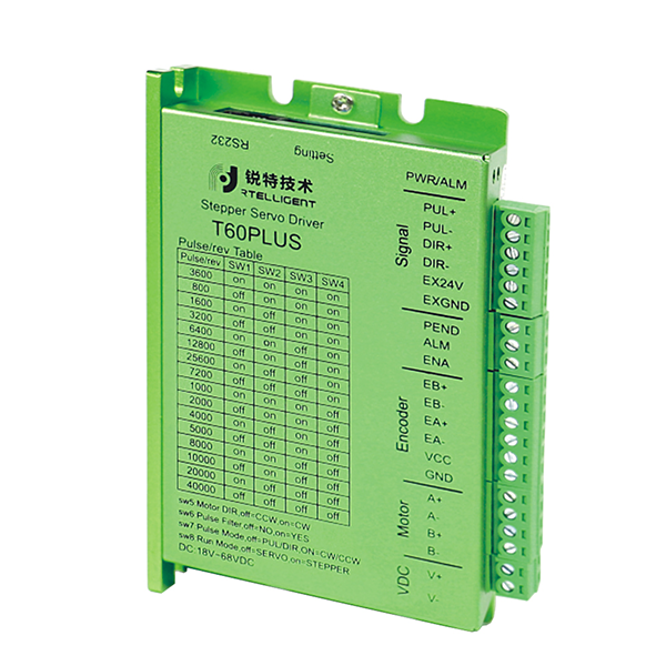
  • PLUS driver with Z signal collector output.
  • PLUS drive increases the Z signal reading and conversion output to realize the Z signal output to PLC.
  • 2-Phase stepper motor 20/28mm series technical specification

    Model Step Angle(○) Holding torque(N.m) Rated current(A) Resistance/phase (ohm) Inductance/phase (mh) Rotor inertia (g.cm2) Shaft diameter(mm) Shaft Length(mm) Length(mm) Weight(Kg)
    20AM003EC 1.8 0.03 0.6 5.7 2.6 3 4 20 46.0 0.09
    28AM006EC 1.8 0.06 1.2 1.4 1.0 90 5 20 44.7 0.13
    28AM013EC 1.8 0.13 1.2 2.2 2.3 180 5 20 63.6 0.22

    2-Phase stepper motor 42mm series technical specification

    Model Step Angle(○) Holding torque(N.m) Rated current(A) Resistance/phase (ohm) Inductance/phase (mh) Rotor inertia (g.cm2) Shaft diameter(mm) Shaft Length(mm) Length(mm) Weight(Kg)
    42A03EC 1.8 0.3 2.0 1.6 1.9 77 8 21 69 0.5
    42A08EC 1.8 0.8 2.8 2.7 2.3 115 8 21 85 0.6
    42AM06ED 1.8 0.6 2.0 1.1 1.5 82 5 24 67 0.4
    42AM08ED 1.8 0.8 2.0 1.9 5 114 5 24 79 0.6

    2-Phase stepper motor 57mm series technical specification

    Model Step Angle(○) Holding torque(N.m) Rated current(A) Resistance/phase (ohm) Inductance/phase (mh) Rotor inertia (g.cm2) Shaft diameter(mm) Shaft Length(mm) Length(mm) Weight(Kg)
    57AM13ED 1.8 1.3 4.0 0.4 1.6 260 8 22 77 0.8
    57AM23ED 1.8 2.3 5.0 0.6 2.4 460 8 22 98 1.2
    57AM26ED 1.8 2.6 5.0 0.5 2.1 520 8 22 106 1.4
    57AM30ED 1.8 2.3 5.0 0.8 3.7 720 8 22 124 1.5
    D57AM30ED 1.8 3.0 5.0 0.5 2.2 690 5 22 107 1.5


    2-Phase stepper motor 60mm series technical specification

    Model Step Angle(○) Holding torque(N.m) Rated current(A) Resistance/phase (ohm) Inductance/phase (mh) Rotor inertia (g.cm2) Shaft diameter(mm) Shaft Length(mm) Length(mm) Weight(Kg)
    60AM22ED 1.8 2.2 5.0 0.4 1.3 330 8 22 79 1.1
    60AM30ED 1.8 3.0 5.0 0.5 2.2 690 8 22 107 1.5
    60AM40ED 1.8 4.0 5.0 0.9 3.5 880 10 30 123 2.1

    2-Phase stepper motor 86mm series technical specification

    Model Step Angle(○) Holding torque(N.m) Rated current(A) Resistance/phase (ohm) Inductance/phase (mh) Rotor inertia (g.cm2) Shaft diameter(mm) Shaft Length(mm) Length(mm) Weight(Kg)
    86AM65ED 1.8 4.5 6.0 0.4 2.8 1400 14 40 105 2.5
    86AM65ED 1.8 6.5 6.0 0.5 4.2 2300 14 40 127 3.3
    86AM85ED 1.8 8.5 6.0 0.5 5.5 2800 14 40 140 3.9
    86AM100ED 1.8 10 6.0 0.8 5.3 3400 14 40 157 4.3
    86AM120ED 1.8 12 6.0 0.7 8.3 4000 14 40 182 5.3

    3-Phase stepper motor 86/110mm series technical specification

    Model Step Angle(○) Holding torque(N.m) Rated current(A) Resistance/phase (ohm) Inductance/phase (mh) Rotor inertia (g.cm2) Shaft diameter(mm) Shaft Length(mm) Length(mm) Weight(Kg)
    86B8EH 1.2 8.0 6.0 2.6 17.4 2940 14 40 150 5.0
    86B10EH 1.2 10 6.0 2.7 18.9 4000 14 40 178 5.8
    110B12EH 1.2 12 4.2 1.2 13.0 10800 19 40 162 9.0
    110B20EH 1.2 20 5.2 1.9 18.0 17000 19 40 244 11.8

    Stepper Servo Drive


    Introduction

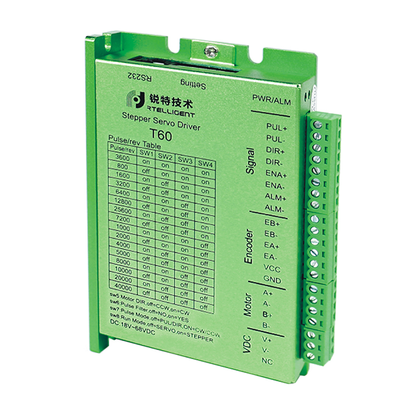
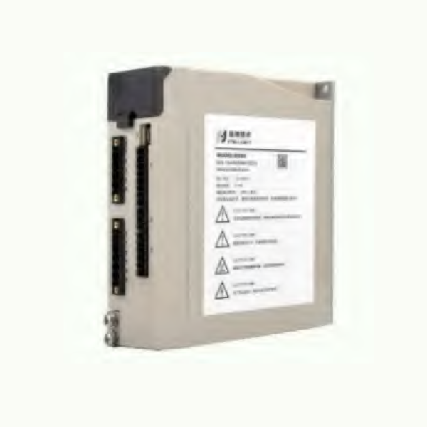
    T series Hybrid Stepper Drive, built on the new DSP hardware platform, uses magnetic field orientation (FOC) and a

    field-weakening control algorithm to perform superior to conventional stepper drives in all areas.

    Diagram

    Hybrid Servo Set

    Naming Rule

    Hybrid Servo Set
    • Phases
      2 phase(omitted)
      3: 3 phase
      5: 5 phase
    • Serial Name
    • Match the motor flange size
    • Upgraded version
      X2: Two-in-one
      X3: Three-in-one
    • Function code
      IO: Switch
      D: One-drive-two

    *Model naming rules are only used for model meaning analysis.
    For specific optional models, please refer to the details page.


    Product Series

    Technical Specification

    Model Peak Current (A) Weight (Kg) Input Voltage Dimensions (mm) Naming of micro-stepping Pulse Level Matching Motor
    T42 3.0 0.2 18-68VDC 116 X 69 X 26.5 800-51200 3.3-24V closed loop below 42mm
    T60 6.0 0.2 18-68VDC 116 X 69 X 26.5 800-51200 3.3-24V closed loop below 60mm
    T60PLUS 6.0 0.3 18-48VDC 118 X 76 X 25 200-25600 3.3-24V closed loop below 60mm
    T86 7.0 0.6 18-80VAC 151 X 97 X 52 400-51200 3.3-24V closed loop below 86mm
    DS86 7.2 0.8 18-80VAC 151 X 141 X 47 400-60000 3.3-24V closed loop below 86mm
    NT110 8.0 1.3 110-230VAC 151 X 141 X 58 400-60000 3.3-24V 3-phase closed loop below 110 mm